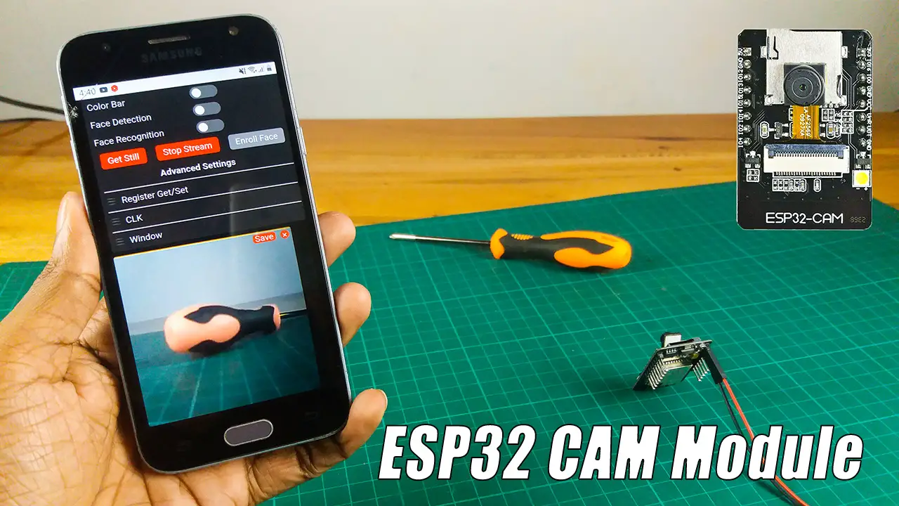
ESP32 Capture image periodic and store in sd card
ESP32-CAM to capture images periodically, you can use the Timer or Delay functionality in the ESP32 code.
Setup Overview:
Hardware Preparation: Ensure the ESP32-CAM module is connected and properly powered.
Image Capture Library: Use the esp_camera library to initialize and capture images.
Timing Mechanism: Use Ticker (or millis for manual implementation) for periodic image capture.
Optional: Store the images to an SD card or send them via HTTP, MQTT, or FTP.
    #include "esp_camera.h"
#include "Arduino.h"

// Camera Pin Configuration (adjust for your ESP32-CAM module)
#define PWDN_GPIO_NUM    -1
#define RESET_GPIO_NUM   -1
#define XCLK_GPIO_NUM     0
#define SIOD_GPIO_NUM    26
#define SIOC_GPIO_NUM    27

#define Y9_GPIO_NUM      35
#define Y8_GPIO_NUM      34
#define Y7_GPIO_NUM      39
#define Y6_GPIO_NUM      36
#define Y5_GPIO_NUM      21
#define Y4_GPIO_NUM      19
#define Y3_GPIO_NUM      18
#define Y2_GPIO_NUM       5
#define VSYNC_GPIO_NUM   25
#define HREF_GPIO_NUM    23
#define PCLK_GPIO_NUM    22

unsigned long lastCaptureTime = 0;
const unsigned long captureInterval = 5000; // Interval in milliseconds (e.g., 5 seconds)

void setup() {
  Serial.begin(115200);

  // Initialize the camera
  camera_config_t config;
  config.ledc_channel = LEDC_CHANNEL_0;
  config.ledc_timer = LEDC_TIMER_0;
  config.pin_d0 = Y2_GPIO_NUM;
  config.pin_d1 = Y3_GPIO_NUM;
  config.pin_d2 = Y4_GPIO_NUM;
  config.pin_d3 = Y5_GPIO_NUM;
  config.pin_d4 = Y6_GPIO_NUM;
  config.pin_d5 = Y7_GPIO_NUM;
  config.pin_d6 = Y8_GPIO_NUM;
  config.pin_d7 = Y9_GPIO_NUM;
  config.pin_xclk = XCLK_GPIO_NUM;
  config.pin_pclk = PCLK_GPIO_NUM;
  config.pin_vsync = VSYNC_GPIO_NUM;
  config.pin_href = HREF_GPIO_NUM;
  config.pin_sscb_sda = SIOD_GPIO_NUM;
  config.pin_sscb_scl = SIOC_GPIO_NUM;
  config.pin_pwdn = PWDN_GPIO_NUM;
  config.pin_reset = RESET_GPIO_NUM;
  config.xclk_freq_hz = 20000000;
  config.pixel_format = PIXFORMAT_JPEG; // JPEG output

  // Frame size (can be changed to FRAMESIZE_QVGA, VGA, etc.)
  if (psramFound()) {
    config.frame_size = FRAMESIZE_UXGA; // Full resolution
    config.jpeg_quality = 10;          // Lower number, higher quality
    config.fb_count = 2;
  } else {
    config.frame_size = FRAMESIZE_SVGA;
    config.jpeg_quality = 12;
    config.fb_count = 1;
  }

  // Camera init
  esp_err_t err = esp_camera_init(&config);
  if (err != ESP_OK) {
    Serial.printf("Camera init failed with error 0x%x", err);
    return;
  }

  Serial.println("Camera initialized successfully!");
}

void loop() {
  unsigned long currentTime = millis();

  // Check if it's time to capture an image
  if (currentTime - lastCaptureTime >= captureInterval) {
    captureImage();
    lastCaptureTime = currentTime;
  }
}

// Function to capture and display image
void captureImage() {
  camera_fb_t *fb = esp_camera_fb_get(); // Capture image
  if (!fb) {
    Serial.println("Camera capture failed");
    return;
  }

  Serial.printf("Image captured! Size: %u bytes\n", fb->len);

  // Example: Release the buffer after use (or store it)
  esp_camera_fb_return(fb);
}

“LVGL is the only framework that I've seen as open source Graphics Library for Microcontrollers. It’s easy to customize, adapts to any design, and the build size is tiny.”
Recent Posts
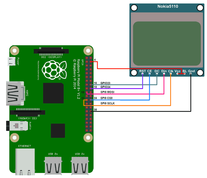
Nokia 5110 LCD with a Raspberry Pi using WiringPi
Nokia 5110 LCD PCD8544 driver with a Raspberry Pi using WiringPi
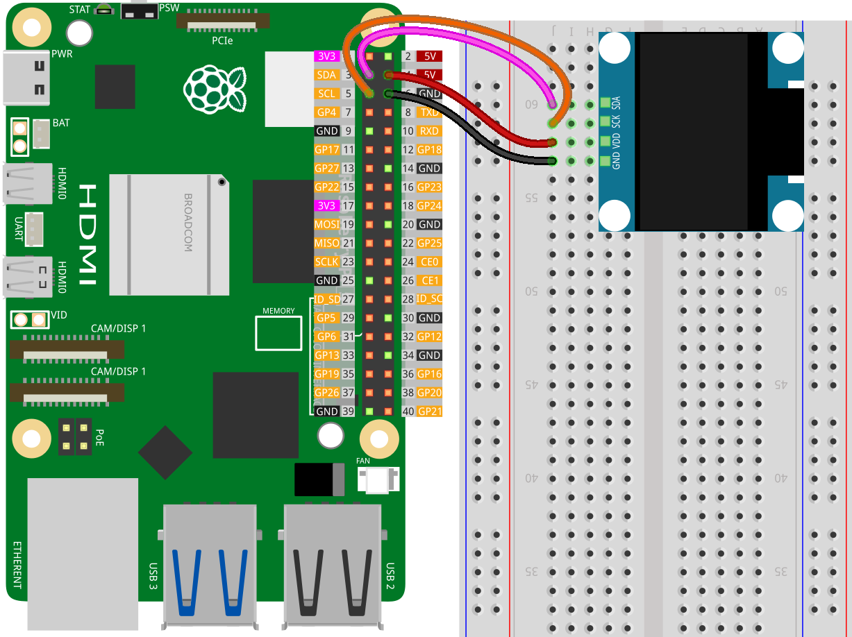
OLED ssd1306 interface with Raspberry Pi using WiringPi
OLED ssd1306 display interface with Raspberry Pi using WiringPi
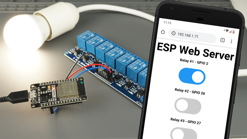
ESP32 lvgl touch display control multiple relay
To control a 4-channel relay using an ESP32 with a touch display (via LVGL library), you can integrate the relay control with a graphical user interface (GUI).
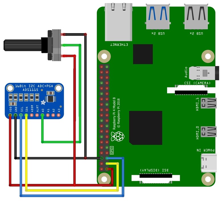
Interface the ADS1115 adc with a Raspberry Pi using WiringPi
Interface the ADS1115 analog-to-digital converter (ADC) with a Raspberry Pi using WiringPi
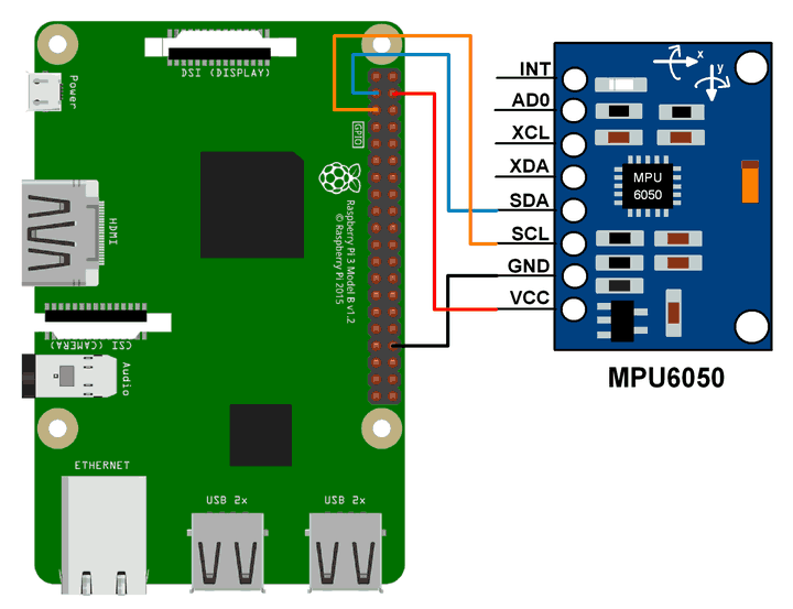
MPU6050 sensor interface with Raspberry Pi using WiringPi
MPU6050 Accelerometer and Gyroscope interface with Raspberry Pi using WiringPi
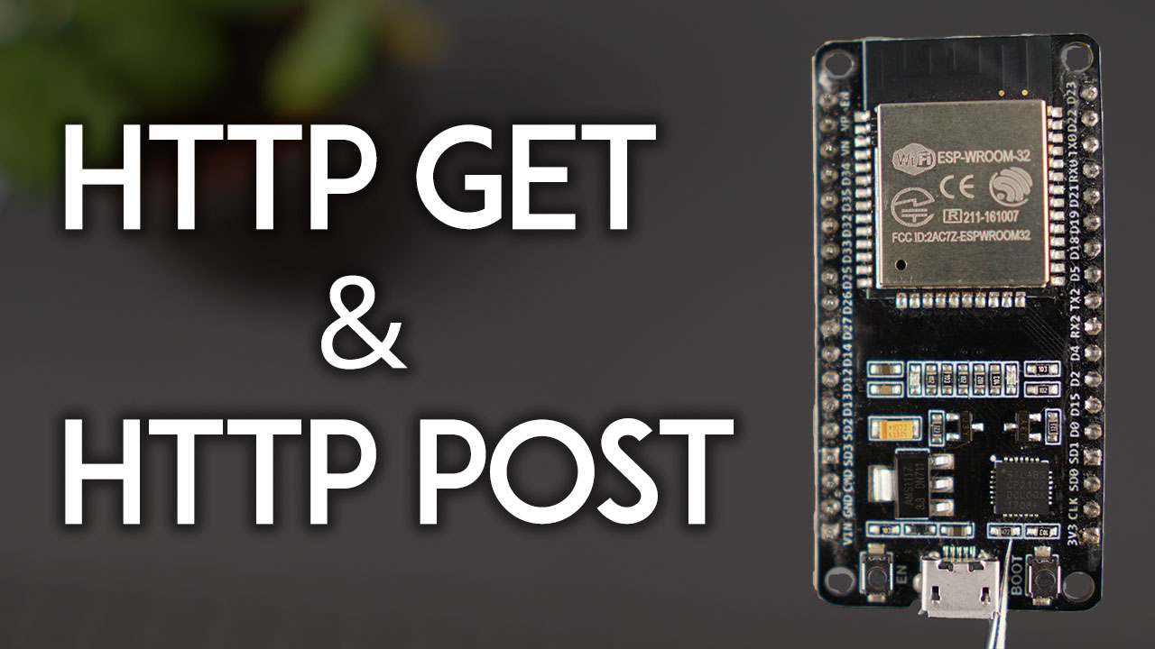
ESP32 Wifi http get and post method request
To perform HTTP GET and HTTP POST requests on an ESP32, you can use the WiFi and HTTPClient libraries.