Interface the ADS1115 adc with a Raspberry Pi using WiringPi
Interface the ADS1115 analog-to-digital converter (ADC) with a Raspberry Pi using WiringPi
Introduction
Here’s a general guide to wiring and using ADS1115 with Raspberry Pi
Wiring (I2C Connection)
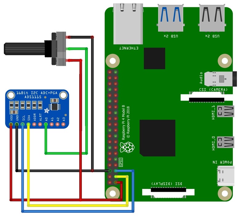
Connect the ADS1115 to the Raspberry Pi as follows:
| ADS1115 Pin | Raspberry Pi Pin (BCM) |
|---|---|
| VDD | 3.3V (Pin 1) |
| GND | GND (Pin 9) |
| SCL | SCL (Pin 5 / GPIO3) |
| SDA | SDA (Pin 3 / GPIO2) |
| ADDR | GND (for address 0x48) |
Steps to Use WiringPi with ADS1115
Install WiringPi (if not installed)
sudo apt update
sudo apt install wiringpi
Enable I2C on Raspberry Pi
Run sudo raspi-config → "Interfacing Options" → Enable I2C.
Check I2C Connection
Ensure the ADS1115 is detected using:
i2cdetect -y 1
You should see an entry at 0x48 (default address).
Read Data via WiringPi
If you're using the i2c command-line tool from WiringPi, try:
gpio i2c 1 0x48 0x00
    #include <stdio.h>
#include <stdint.h>
#include <wiringPi.h>
#include <wiringPiI2C.h>
#include "ads1115.h"

#define BASE 100
int main()
{

int16_t value;
  double voltage;
  ads1115Setup(BASE,0x49);

  for (;;) {
    value = (int16_t) analogRead(100);
    voltage = value * (4.096 / 32768);

    printf("ADS1115 Reading: %d\n\r",value);
    printf("ADS1115 Voltage: %g\n\r",voltage);
    delay(1000);
}
	return 0 ;
}
ADC header
    #include <byteswap.h>
#include <stdio.h>
#include <stdint.h>

#include <wiringPi.h>
#include <wiringPiI2C.h>

#include "ads1115.h"

// Bits in the config register (it's a 16-bit register)

#define	CONFIG_OS_MASK		(0x8000)	// Operational Status Register
#define	CONFIG_OS_SINGLE	(0x8000)	// Write - Starts a single-conversion
						// Read    1 = Conversion complete

// The multiplexor

#define	CONFIG_MUX_MASK		(0x7000)

// Differential modes

#define	CONFIG_MUX_DIFF_0_1	(0x0000)	// Pos = AIN0, Neg = AIN1 (default)
#define	CONFIG_MUX_DIFF_0_3	(0x1000)	// Pos = AIN0, Neg = AIN3
#define	CONFIG_MUX_DIFF_1_3	(0x2000)	// Pos = AIN1, Neg = AIN3
#define	CONFIG_MUX_DIFF_2_3	(0x3000)	// Pos = AIN2, Neg = AIN3 (2nd differential channel)

// Single-ended modes

#define	CONFIG_MUX_SINGLE_0	(0x4000)	// AIN0
#define	CONFIG_MUX_SINGLE_1	(0x5000)	// AIN1
#define	CONFIG_MUX_SINGLE_2	(0x6000)	// AIN2
#define	CONFIG_MUX_SINGLE_3	(0x7000)	// AIN3

// Programmable Gain Amplifier

#define	CONFIG_PGA_MASK		(0x0E00)
#define	CONFIG_PGA_6_144V	(0x0000)	// +/-6.144V range = Gain 2/3
#define	CONFIG_PGA_4_096V	(0x0200)	// +/-4.096V range = Gain 1
#define	CONFIG_PGA_2_048V	(0x0400)	// +/-2.048V range = Gain 2 (default)
#define	CONFIG_PGA_1_024V	(0x0600)	// +/-1.024V range = Gain 4
#define	CONFIG_PGA_0_512V	(0x0800)	// +/-0.512V range = Gain 8
#define	CONFIG_PGA_0_256V	(0x0A00)	// +/-0.256V range = Gain 16

#define	CONFIG_MODE		(0x0100)	// 0 is continuous, 1 is single-shot (default)

// Data Rate

#define	CONFIG_DR_MASK		(0x00E0)
#define	CONFIG_DR_8SPS		(0x0000)	//   8 samples per second
#define	CONFIG_DR_16SPS		(0x0020)	//  16 samples per second
#define	CONFIG_DR_32SPS		(0x0040)	//  32 samples per second
#define	CONFIG_DR_64SPS		(0x0060)	//  64 samples per second
#define	CONFIG_DR_128SPS	(0x0080)	// 128 samples per second (default)
#define	CONFIG_DR_475SPS	(0x00A0)	// 475 samples per second
#define	CONFIG_DR_860SPS	(0x00C0)	// 860 samples per second

// Comparator mode

#define	CONFIG_CMODE_MASK	(0x0010)
#define	CONFIG_CMODE_TRAD	(0x0000)	// Traditional comparator with hysteresis (default)
#define	CONFIG_CMODE_WINDOW	(0x0010)	// Window comparator

// Comparator polarity - the polarity of the output alert/rdy pin

#define	CONFIG_CPOL_MASK	(0x0008)
#define	CONFIG_CPOL_ACTVLOW	(0x0000)	// Active low (default)
#define	CONFIG_CPOL_ACTVHI	(0x0008)	// Active high

// Latching comparator - does the alert/rdy pin latch

#define	CONFIG_CLAT_MASK	(0x0004)
#define	CONFIG_CLAT_NONLAT	(0x0000)	// Non-latching comparator (default)
#define	CONFIG_CLAT_LATCH	(0x0004)	// Latching comparator

// Comparitor queue

#define	CONFIG_CQUE_MASK	(0x0003)
#define	CONFIG_CQUE_1CONV	(0x0000)	// Assert after one conversions
#define	CONFIG_CQUE_2CONV	(0x0001)	// Assert after two conversions
#define	CONFIG_CQUE_4CONV	(0x0002)	// Assert after four conversions
#define	CONFIG_CQUE_NONE	(0x0003)	// Disable the comparator (default)

#define	CONFIG_DEFAULT		(0x8583)	// From the datasheet


static const uint16_t dataRates [8] =
{
  CONFIG_DR_8SPS, CONFIG_DR_16SPS, CONFIG_DR_32SPS, CONFIG_DR_64SPS, CONFIG_DR_128SPS, CONFIG_DR_475SPS, CONFIG_DR_860SPS
} ;

static const uint16_t gains [6] =
{
  CONFIG_PGA_6_144V, CONFIG_PGA_4_096V, CONFIG_PGA_2_048V, CONFIG_PGA_1_024V, CONFIG_PGA_0_512V, CONFIG_PGA_0_256V
} ;


/*
 * analogRead:
 *	Pin is the channel to sample on the device.
 *	Channels 0-3 are single ended inputs,
 *	channels 4-7 are the various differential combinations.
 *********************************************************************************
 */

static int myAnalogRead (struct wiringPiNodeStruct *node, int pin)
{
  int chan = pin - node->pinBase ;
  int16_t  result ;
  uint16_t config = CONFIG_DEFAULT ;

  chan &= 7 ;

// Setup the configuration register

//	Set PGA/voltage range

  config &= ~CONFIG_PGA_MASK ;
  config |= node->data0 ;

//	Set sample speed

  config &= ~CONFIG_DR_MASK ;
  config |= node->data1 ;

//	Set single-ended channel or differential mode

  config &= ~CONFIG_MUX_MASK ;

  switch (chan)
  {
    case 0: config |= CONFIG_MUX_SINGLE_0 ; break ;
    case 1: config |= CONFIG_MUX_SINGLE_1 ; break ;
    case 2: config |= CONFIG_MUX_SINGLE_2 ; break ;
    case 3: config |= CONFIG_MUX_SINGLE_3 ; break ;

    case 4: config |= CONFIG_MUX_DIFF_0_1 ; break ;
    case 5: config |= CONFIG_MUX_DIFF_2_3 ; break ;
    case 6: config |= CONFIG_MUX_DIFF_0_3 ; break ;
    case 7: config |= CONFIG_MUX_DIFF_1_3 ; break ;
  }

//	Start a single conversion

  config |= CONFIG_OS_SINGLE ;
  config = __bswap_16 (config) ;
  wiringPiI2CWriteReg16 (node->fd, 1, config) ;

// Wait for the conversion to complete

  for (;;)
  {
    result =  wiringPiI2CReadReg16 (node->fd, 1) ;
    result = __bswap_16 (result) ;
    if ((result & CONFIG_OS_MASK) != 0)
      break ;
    delayMicroseconds (100) ;
  }

  result =  wiringPiI2CReadReg16 (node->fd, 0) ;
  result = __bswap_16 (result) ;

// Sometimes with a 0v input on a single-ended channel the internal 0v reference
//	can be higher than the input, so you get a negative result...

  if ( (chan < 4) && (result < 0) )
    return 0 ;
  else
    return (int)result ;
}


/*
 * digitalWrite:
 *	It may seem odd to have a digital write here, but it's the best way
 *	to pass paramters into the chip in the wiringPi way of things.
 *	We have 2 digital registers:
 *		0 is the gain control
 *		1 is the data rate control
 *********************************************************************************
 */

static void myDigitalWrite (struct wiringPiNodeStruct *node, int pin, int data)
{
  int chan = pin - node->pinBase ;
  chan &= 3 ;

  if (chan == 0)	// Gain Control
  {
    if ( (data < 0) || (data > 6) )	// Use default if out of range
      data = 2 ;
    node->data0 = gains [data] ;
  }
  else			// Data rate control
  {
    if ( (data < 0) || (data > 7) )	// Use default if out of range
      data = 4 ;
    node->data1 = dataRates [data] ;	// Bugfix 0-1 by "Eric de jong (gm)" <[email protected]> - Thanks.
  }

}


/*
 * analogWrite:
 *	We're using this to write to the 2 comparitor threshold registers.
 *	We could use a digitalWrite here but as it's an analog comparison
 *	then it feels better to do it this way.
 *********************************************************************************
 */

static void myAnalogWrite (struct wiringPiNodeStruct *node, int pin, int data)
{
  int chan = pin - node->pinBase ;
  int reg ;
  int16_t ndata ;

  chan &= 3 ;

  reg = chan + 2 ;

  /**/ if (data < -32767)
    ndata = -32767 ;
  else if (data > 32767)
    ndata = 32767 ;
  else
    ndata = (int16_t)data ;

  ndata = __bswap_16 (ndata) ;
  wiringPiI2CWriteReg16 (node->fd, reg, data) ;
}


/*
 * ads1115Setup:
 *	Create a new wiringPi device node for an ads1115 on the Pi's
 *	I2C interface.
 *********************************************************************************
 */

int ads1115Setup (const int pinBase, int i2cAddr)
{
  struct wiringPiNodeStruct *node ;
  int fd ;

  if ((fd = wiringPiI2CSetup (i2cAddr)) < 0)
    return 0 ;

  node = wiringPiNewNode (pinBase, 8) ;

  node->fd           = fd ;
  node->data0        = CONFIG_PGA_4_096V ;	// Gain in data0
  node->data1        = CONFIG_DR_128SPS ;	// Samples/sec in data1
  node->analogRead   = myAnalogRead ;
  node->analogWrite  = myAnalogWrite ;
  node->digitalWrite = myDigitalWrite ;

  return 1 ;
}
    // Constants for some of the internal functions

//	Gain

#define	ADS1115_GAIN_6		0
#define	ADS1115_GAIN_4		1
#define	ADS1115_GAIN_2		2
#define	ADS1115_GAIN_1		3
#define	ADS1115_GAIN_HALF	4
#define	ADS1115_GAIN_QUARTER	5

//	Data rate

#define	ADS1115_DR_8		0
#define	ADS1115_DR_16		1
#define	ADS1115_DR_32		2
#define	ADS1115_DR_64		3
#define	ADS1115_DR_128		4
#define	ADS1115_DR_250		5
#define	ADS1115_DR_475		6
#define	ADS1115_DR_860		7

#ifdef __cplusplus
extern "C" {
#endif

extern int ads1115Setup (int pinBase, int i2cAddress) ;

#ifdef __cplusplus
}
#endif

“LVGL is the only framework that I've seen as open source Graphics Library for Microcontrollers. It’s easy to customize, adapts to any design, and the build size is tiny.”
Recent Posts
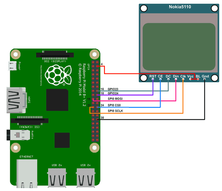
Nokia 5110 LCD with a Raspberry Pi using WiringPi
Nokia 5110 LCD PCD8544 driver with a Raspberry Pi using WiringPi
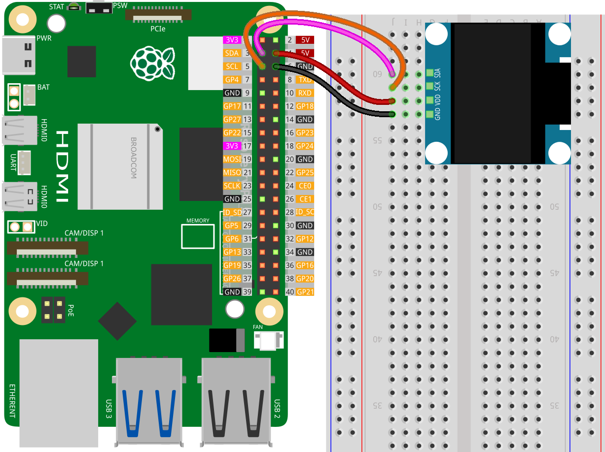
OLED ssd1306 interface with Raspberry Pi using WiringPi
OLED ssd1306 display interface with Raspberry Pi using WiringPi
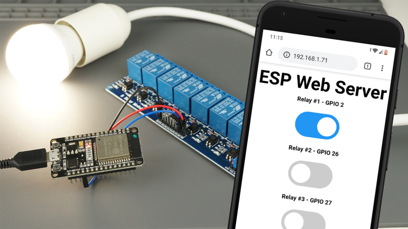
ESP32 lvgl touch display control multiple relay
To control a 4-channel relay using an ESP32 with a touch display (via LVGL library), you can integrate the relay control with a graphical user interface (GUI).
Interface the ADS1115 adc with a Raspberry Pi using WiringPi
Interface the ADS1115 analog-to-digital converter (ADC) with a Raspberry Pi using WiringPi
MPU6050 sensor interface with Raspberry Pi using WiringPi
MPU6050 Accelerometer and Gyroscope interface with Raspberry Pi using WiringPi

ESP32 Wifi http get and post method request
To perform HTTP GET and HTTP POST requests on an ESP32, you can use the WiFi and HTTPClient libraries.