Overview of MPU6050 Sensor
The MPU6050 sensor module is a widely used 6-axis motion tracking device, integrating the following components:
- 3-axis Accelerometer – Measures acceleration in the X, Y, and Z axes in units of g.
- 3-axis Gyroscope – Measures angular velocity in degrees per second (dps).
- Digital Motion Processor (DMP) – Handles complex computations internally to offload the microcontroller.
- Temperature Sensor – Provides onboard temperature monitoring.
- Auxiliary I2C Bus – Allows connection of additional sensors, such as a 3-axis magnetometer or pressure sensor, to provide a full 9-axis motion fusion output.
Key Features of MPU6050:
- Communication: I2C (Inter-Integrated Circuit) protocol.
- Operating Voltage: 3.3V to 5V.
- Measurement Range:
- Accelerometer: ±2g, ±4g, ±8g, ±16g.
- Gyroscope: ±250, ±500, ±1000, ±2000 degrees/sec.
- Data Format: 2’s complement form.
- Address Selection: Default I2C address is
0x68 (can be changed to 0x69 by connecting AD0 to VCC).
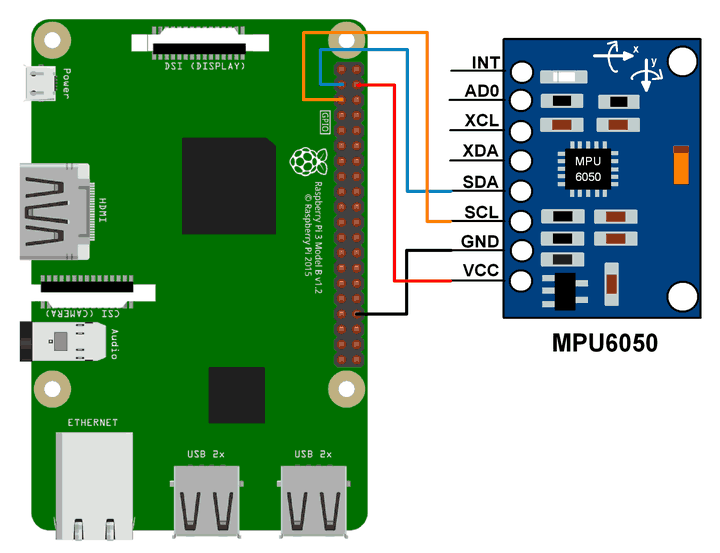
Wiring (I2C Connection)
Connect the MPU6050 to the Raspberry Pi as follows:
| MPU6050 Pin |
Raspberry Pi Pin (BCM) |
Function |
| SCL |
GPIO3 (Pin 5) |
I2C Clock (SCL) |
| SDA |
GPIO2 (Pin 3) |
I2C Data (SDA) |
| AD0 |
GND (For 0x68 address) |
Address Select |
Steps to Use WiringPi with MPU6050
- 3-axis Accelerometer – Measures acceleration in the X, Y, and Z axes in units of g.
- 3-axis Gyroscope – Measures angular velocity in degrees per second (dps).
- Digital Motion Processor (DMP) – Handles complex computations internally to offload the microcontroller.
- Temperature Sensor – Provides onboard temperature monitoring.
- Auxiliary I2C Bus – Allows connection of additional sensors, such as a 3-axis magnetometer or pressure sensor, to provide a full 9-axis motion fusion output.
Key Features of MPU6050:
- Communication: I2C (Inter-Integrated Circuit) protocol.
- Operating Voltage: 3.3V to 5V.
- Measurement Range:
- Accelerometer: ±2g, ±4g, ±8g, ±16g.
- Gyroscope: ±250, ±500, ±1000, ±2000 degrees/sec.
- Data Format: 2’s complement form.
- Address Selection: Default I2C address is
0x68 (can be changed to 0x69 by connecting AD0 to VCC).
Wiring (I2C Connection)
Connect the MPU6050 to the Raspberry Pi as follows:
| MPU6050 Pin |
Raspberry Pi Pin (BCM) |
Function |
| SCL |
GPIO3 (Pin 5) |
I2C Clock (SCL) |
| SDA |
GPIO2 (Pin 3) |
I2C Data (SDA) |
| AD0 |
GND (For 0x68 address) |
Address Select |
Steps to Use WiringPi withMPU6050
Install WiringPi (if not installed)
sudo apt update
sudo apt install wiringpi
Enable I2C on Raspberry Pi
Run sudo raspi-config → "Interfacing Options" → Enable I2C.
Check I2C Connection
Ensure the ADS1115 is detected using:
i2cdetect -y 1
You should see an entry at 0x68 (default address).
Read Data via WiringPi
If you're using the i2c command-line tool from WiringPi, try:
gpio i2c 1 0x68 0x00
#include <stdio.h>
#include <stdint.h>
#include <wiringPi.h>
#include <wiringPiI2C.h>
#define MPU6050_ACCEL_XOUT_H 0x3B
#define MPU6050_ACCEL_YOUT_H 0x3D
#define MPU6050_ACCEL_ZOUT_H 0x3F
#define MPU6050_GYRO_XOUT_H 0x43
#define MPU6050_GYRO_YOUT_H 0x45
#define MPU6050_GYRO_ZOUT_H 0x47
#define MPU6050_PWR_MGMT_1 0x6B
#define MPU6050_I2C_ADDRESS 0x68
int main()
{
int fd = wiringPiI2CSetup(MPU6050_I2C_ADDRESS);
if (fd == -1){
return 0;
}
wiringPiI2CReadReg8(fd, MPU6050_PWR_MGMT_1);
wiringPiI2CWriteReg16(fd, MPU6050_PWR_MGMT_1, 0);
signed long int x,y,z;
signed long int ax,ay,az;
while(1)
{
ax = wiringPiI2CReadReg8(fd, MPU6050_ACCEL_XOUT_H);
ay = wiringPiI2CReadReg8(fd, MPU6050_ACCEL_YOUT_H);
az = wiringPiI2CReadReg8(fd, MPU6050_ACCEL_ZOUT_H);
x = wiringPiI2CReadReg8(fd, MPU6050_GYRO_XOUT_H);
y = wiringPiI2CReadReg8(fd, MPU6050_GYRO_YOUT_H);
z = wiringPiI2CReadReg8(fd, MPU6050_GYRO_ZOUT_H);
printf("Accel x=%li Accel y=%li Accel z=%li \n", ax,ay,az);
printf("Gyro x=%li Gyro y=%li Gyro z=%li \n", x,y,z);
delay(500);
}
return 0;
}